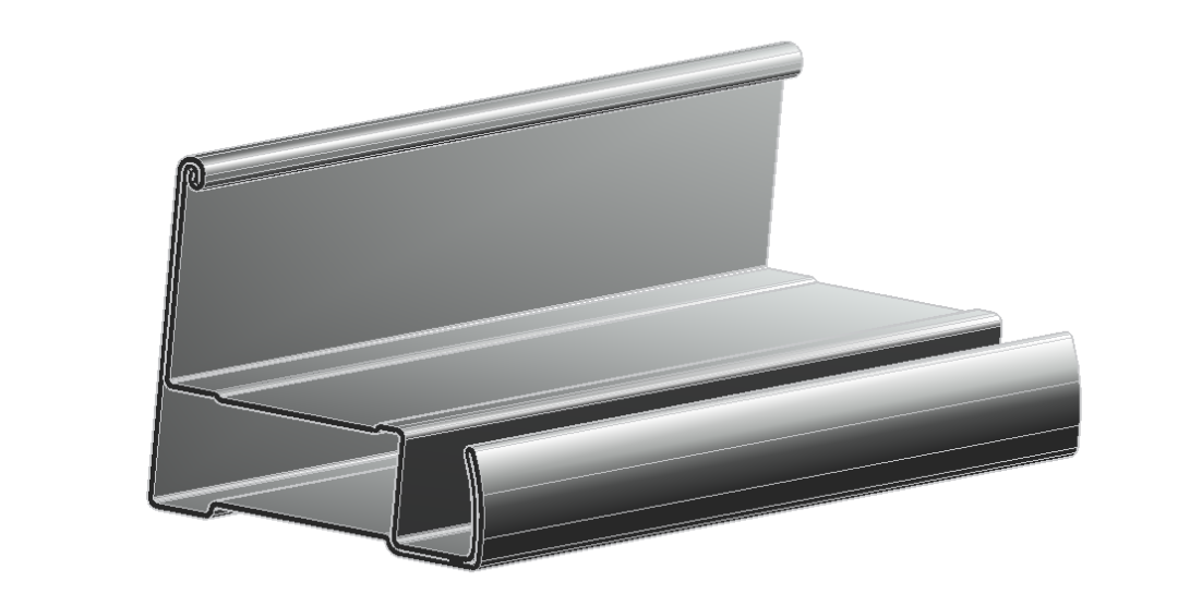
Introduction of New Aluminum Solar PV Panel Frames
L-shaped closed steel frame (photovoltaic panel frame), using the design and simulation module of Copra software, showing the powerful design and accurate simulation analysis functions, improving the design efficiency, and reducing the error costs.
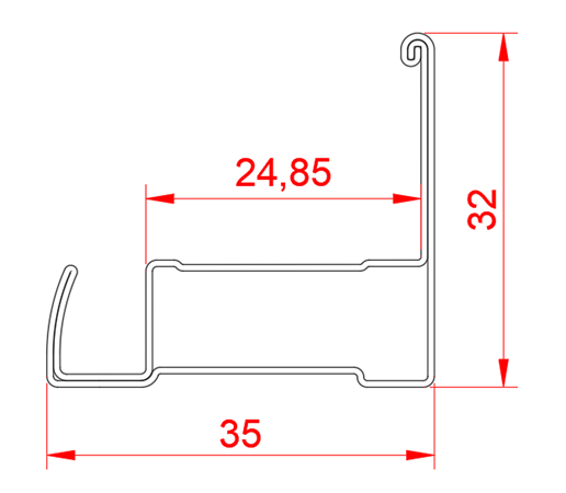
Parameter of New Aluminum Solar PV Panel Frames
Copra software provides a variety of board width calculation methods (such as standard formula and DIN6935, both methods are used in this case). According to the final product section, the initial feed board width is 155.49mm.
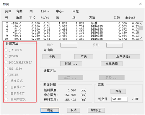

The surface of the feed strip is galvanized magnesium-aluminum coating, the yield strength is 365MPa, the tensile strength is 490MPa, the elongation is 16%, the Poisson’s ratio is 0.3, and the Young’s modulus is 210GPa.
The knurled design of New Aluminum Solar PV Panel Frames
The number of roll forming passes of this section is 41.
The software provides a variety of unfolding forming methods for corner unfolding. This section adopts two methods: constant length of neutral layer and fixed radius.
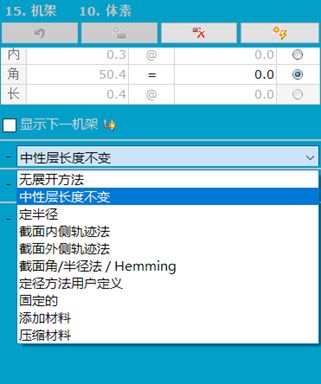
The software provides a convenient roll design-spreadsheet function, which can help engineers to quickly develop and modify the section.
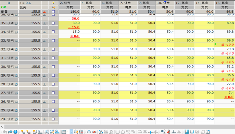
The Roller flower rationality verification of New Aluminum Solar PV Panel Frames
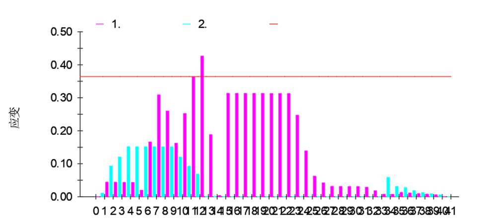
The software provides a rapid verification tool for the rationality of the roll pattern design. The state of the strip after each pass is shown in the figure, and the longitudinal strain of the edge of the strip is displayed in different colors when it passes through each pass.
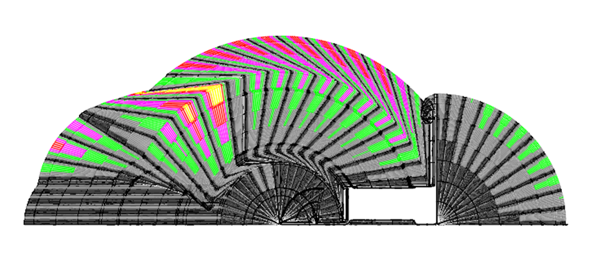
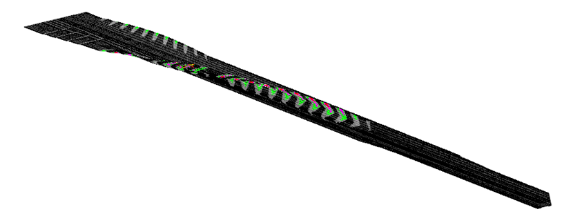
The longitudinal strain value of each pass is displayed in the form of a bar chart, which is used to verify whether the forming angle and forming number of each corner are reasonable. As shown in the figure, the forming longitudinal strain of each pass meets the design requirements.
Roll Design of New Aluminum Solar PV Panel Frames
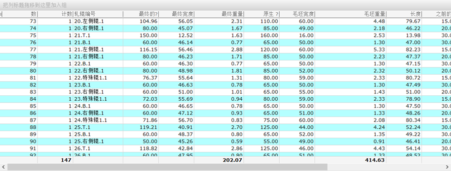
The software provides a variety of roll design and correction functions, which can quickly obtain the matching roll drawings, and can quickly export the drawings and roll weights. As shown in the figure, the blank width and diameter can be quickly obtained. The blank weight is about 414.63Kg.
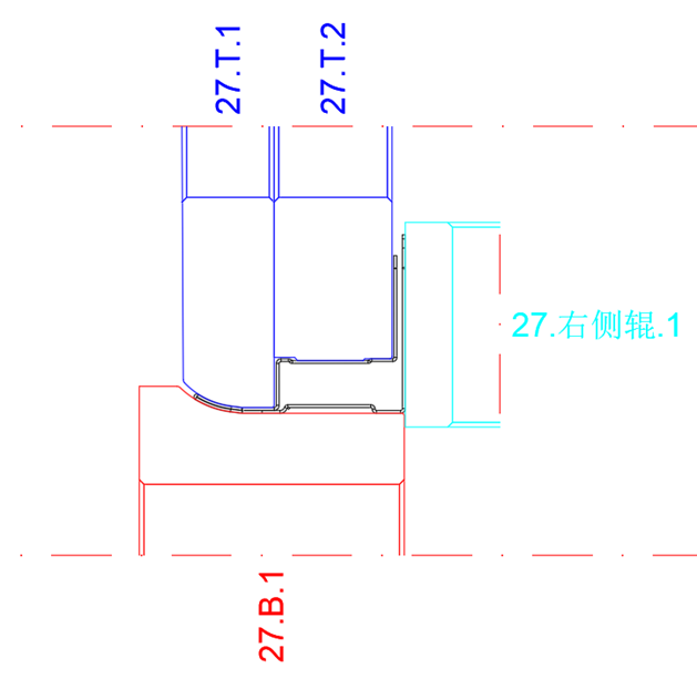
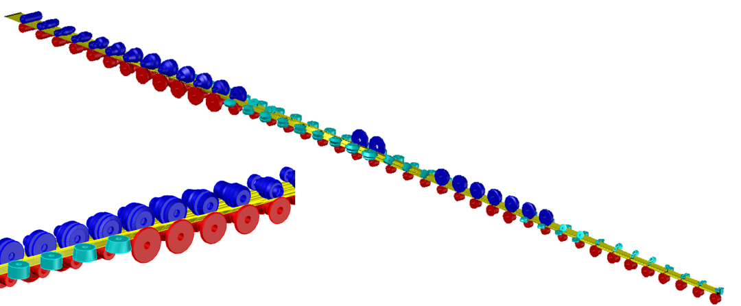
The software can quickly convert the designed two-dimensional graphics into three-dimensional entities, and quickly check whether the arrangement of the rolls is reasonable and the forming characteristics of the sheet, as shown in the figure below.
Simulation of New Aluminum Solar PV Panel Frames
Through Copra software, design drawing files can be quickly converted into finite element models, and calculations can be submitted quickly, reducing the operation process from design to simulation.
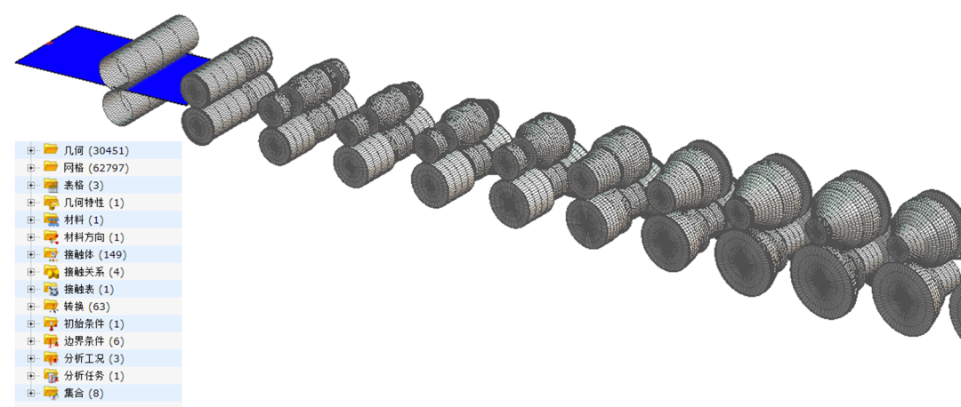
Simulation Results of New Aluminum Solar PV Panel Frames
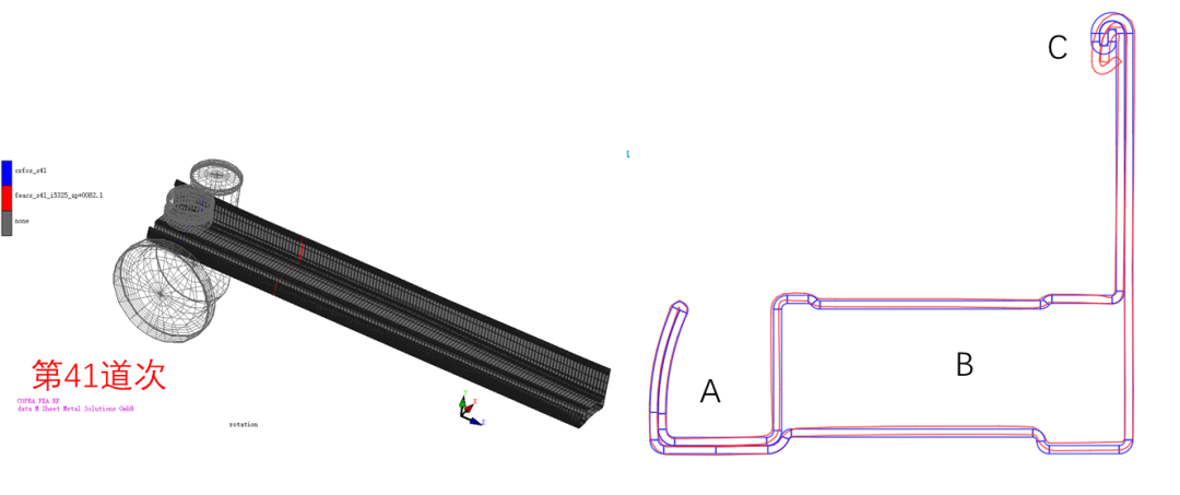
The software provides a cross-section comparison function, that is, the cross-section of the simulated strip passing through each pass is compared with the cross-section of each pass designed by the user. The picture shows the cross-section comparison of the 5th pass. The red curve is the cross-section of the simulated strip, the blue is the cross-section designed by the user, and the green is the cross-section of the simulated strip after rolling out of the roll.
Users can check the transverse flow of the strip, the springback of the strip after it rolls out of the roll, and the shape of the strip at each moment, and can measure the extension distance and springback angle of the strip. Through the cross-sectional comparison, it can be seen that the R angle at A rolls back out of the roll.

When the profile is rolled out of the last pass, the cross section of the simulated strip (red) is extracted and compared with the design section of the last pass (blue). By comparison, it can be seen that the profiles in area A are well formed and meet the design requirements; the profiles in area B are slightly deviated from the design due to the springback and the forming force of other parts; the profiles in area C are not ideally formed, because the profiles are in The lateral flow of material occurs during the molding process, so the size of the profile at this position has deviated from the design size before the C area is formed, and further optimization of the design is required.
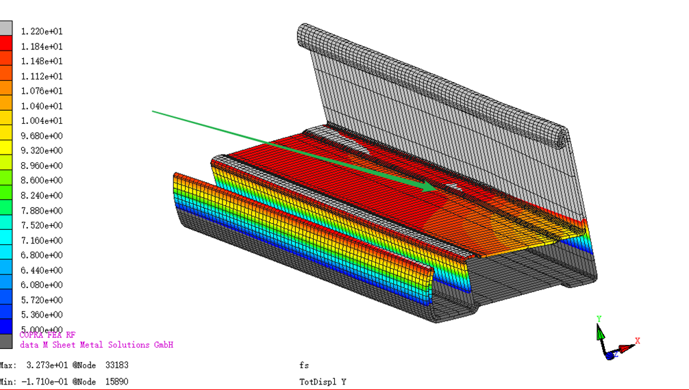
When the profile is rolled out for the last pass, the front end of the feed is cut off, leaving the profile as shown in the figure, showing the Y-direction cloud map (thickness direction). It can be seen that the middle position of the profile (indicated by the arrow) is bulging. Since the diameter of the lower roll in all passes is fixed, the profile may be longitudinally squeezed when entering the roll. In the later optimization, the method of increasing the diameter of the lower roller can be used to keep the profile in a stretched state.
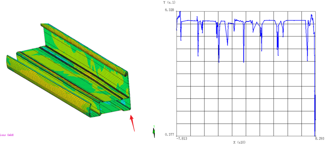
When the profile is rolled out for the last pass, the front end of the feed is cut off, and the thickness variation curve of the profile is extracted. As shown in the figure, the thickness of the corner area is reduced, and the specific size can be viewed in the longitudinal coordinate value.
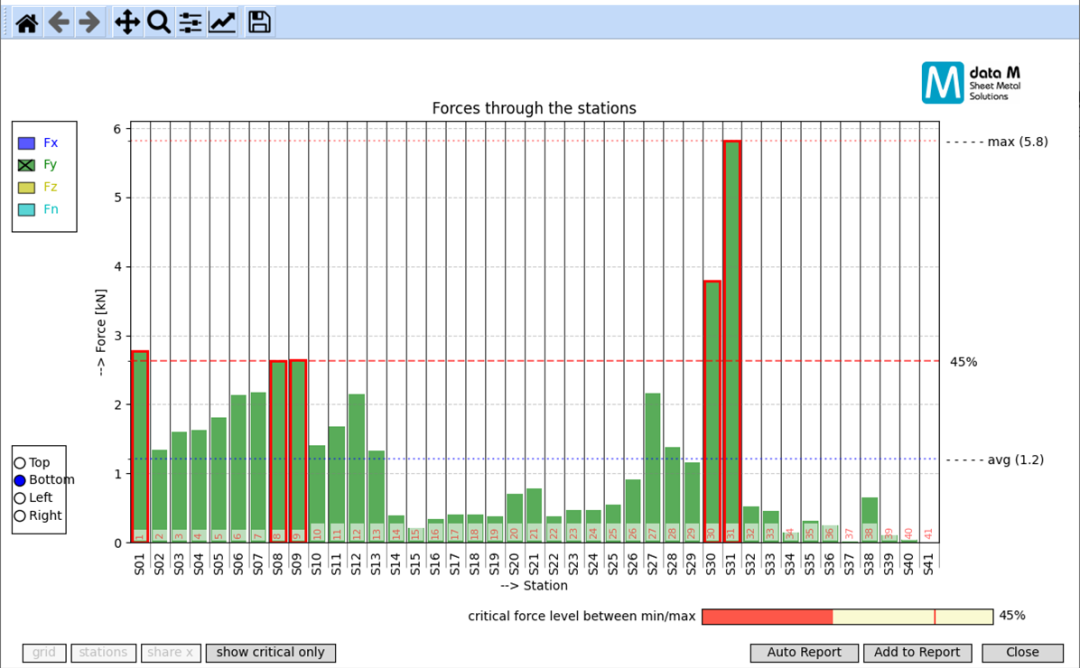
Through the Copra software, the force of the rollers in each pass can be viewed (all passes, up and down, left and right and inclined roller axes, different directions). As shown in the figure, it is the force in the Y direction (thickness direction) of the roller under all passes, which is also the maximum force direction of the roller. It can be seen that when the profile passes through 31 passes, the lower roller is the most stressed, and the force value is about 0.58 tons. The user can judge whether the roll shaft diameter meets the design requirements.
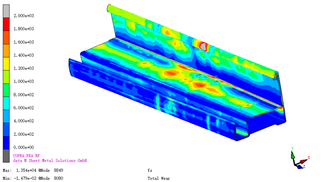
The wear of the profile after passing through the rolls can be viewed through the Copra software.
